
How Is a Ductile Iron Pipe Joint Sealed?
Understanding the Mechanical and Pressure-Assisted Sealing Mechanism
In pressurized pipeline systems, joint integrity is more critical than pipe wall strength.
A pipeline rarely fails through the barrel — it fails at the connection.
So how does a ductile iron pipe joint maintain a watertight seal under internal pressure, soil movement, and long-term operation?
The answer lies in a combination of geometric design, elastic deformation, and pressure interaction.
If you would like to review structural variations such as push-on, restrained, or self-anchored joints, see the technical overview of ductile iron pipe joint systems available in our connection section.

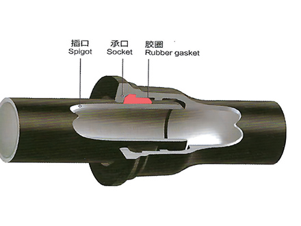
Sealing Is Created by Controlled Radial Compression
At the heart of the joint is a precisely designed geometry:
The socket contains a gasket chamber
The rubber gasket is pre-positioned in this chamber
The spigot enters and compresses the gasket
Unlike metal-to-metal sealing, ductile iron joints rely on elastic deformation.
When the spigot is inserted:
The gasket is compressed radially
Elastic restoring force is generated
Continuous circumferential pressure is formed
This radial pressure creates the primary sealing barrier.
The effectiveness of the seal depends on controlled compression — not excessive force.
2. Internal Pressure Does Not “Push the Joint Apart”
A common misunderstanding is that internal pressure tends to weaken pipe joints.
In properly installed ductile iron push-on systems, the opposite occurs within design limits.
When internal pressure rises:
Fluid pressure acts against the internal surface
The spigot experiences slight outward force
The gasket is pressed more firmly against sealing surfaces
This interaction increases contact pressure between gasket and metal.
In engineering terms, this is known as a pressure-responsive sealing behavior.
In practical operation:
Higher internal pressure → Increased sealing contact stress → Reduced leakage risk
(as long as thrust forces are properly restrained)
3. The Role of Geometry in Sealing Stability
The socket profile is not cylindrical by accident.
It is engineered to:
Guide insertion
Control gasket deformation
Maintain stable compression zones
The geometry ensures that the gasket:
Does not roll easily
Maintains uniform thickness after compression
Resists displacement under pressure
Sealing reliability is therefore a result of coordinated shape design between socket, spigot, and gasket.
4. Why Flexible Joints Improve Long-Term Safety
Ductile iron pipe joints are categorized as flexible connections.
This does not mean they are weak — it means they can accommodate movement.
In real-world conditions:
Soil settlement is common
Traffic load affects buried pipelines
Temperature variation causes dimensional change
A fully rigid joint would transfer these movements into concentrated stress.
Flexible joints, however:
Allow limited angular adjustment
Maintain gasket compression under slight displacement
Reduce structural stress concentration
This ability to adapt without losing sealing pressure is a key reason ductile iron pipe systems are widely used in municipal infrastructure.
To better understand the differences between flexible and restrained configurations, refer to the detailed comparison of ductile iron pipe connection types in our joint section.
5. Sealing Reliability Is a System, Not a Single Component
A ductile iron pipe joint achieves sealing through the combined effect of:
Elastic gasket compression
Pressure-assisted contact force
Optimized socket-spigot geometry
Flexible structural tolerance
It is not dependent on adhesives, mechanical bolts, or rigid locking alone.
When properly installed and supported, the system becomes self-stabilizing under working pressure.
Technical Perspective Summary
A ductile iron pipe joint is sealed because:
The gasket is elastically compressed between matched metal profiles
Internal pressure enhances rather than weakens contact force
Flexible design accommodates real-world movement without losing compression
This integrated sealing principle explains the long-term reliability of ductile iron pipe systems in pressurized water infrastructure.
 GT-type Joint Ductile Iron Pipe
 Sewage Pipe (Ductile Iron Sewage Pipe)
 Special Coating Pipe (Ductile Iron Pipe with Special Coatings)