Successful ductile iron pipe joint installation relies on six core controllable factors: accurate rubber gasket placement, thorough spigot/socket cleaning, full insertion to standard depth, controlled joint deflection, uniform bedding support around joints, and adequate axial thrust restraint.
Nearly all pipeline joint leakage, settlement deformation and post-project rework stem from field installation errors rather than defective pipe products. This complete installation guide breaks down frequently ignored construction details, standardized checklists and troubleshooting tips to help engineers and construction crews deliver leak-free, long-service ductile iron pipeline systems.
Why Proper Ductile Iron Pipe Joint Installation Matters
Push-on ductile iron pipe joints are engineered for stable sealing and structural bearing capacity. However, minor careless operations on-site will create hidden risks that only surface during pressure testing or years after project handover: water seepage, uneven pipe settlement, gasket aging damage and costly secondary excavation rework.
High-grade ductile iron pipes and matching rubber gaskets cannot guarantee pipeline reliability alone. Strict execution of standardized joint installation procedures eliminates over 95% of common joint failure risks. Below is a full operational guide covering pre-installation preparation, six critical overlooked construction points, mistake summary table and frequently asked technical questions.
For professional reference on ductile iron pipe joint types and complete connection systems, check:
👉 Ductile Iron Pipe Joints & Connections
Before Installation: Mandatory Pre-Job Checklist
Complete all items below before assembling any pipe joint;
✅ Visual inspection: No cracks, dents or chipping on spigot and socket ends
✅ Socket inner groove fully cleared of sand, mud and rust debris
✅ Rubber gasket intact, free of cuts, aging deformation or twisting
✅ Manufacturer-specified compatible lubricant prepared on-site
✅ Joint model, nominal diameter and deflection limit match project design drawings
✅ Trench flatness and temporary pipe alignment pre-adjusted
6 Commonly Overlooked Installation Inspection Points
1. Incorrect Rubber Gasket Installation
Problem
Rubber gasket twisted, flipped or installed back-to-front
Gasket not fully locked into the socket sealing groove
Sand, gravel or construction mud trapped between gasket and groove wall
Why It Matters
Trapped impurities and uneven gasket placement cause inconsistent compression under pipeline internal pressure. Weak sealing zones will trigger leakage during hydrostatic testing and accelerate irreversible gasket abrasion.
Best Practice
Unfold the gasket fully to confirm no twisting before placement
Press the entire gasket evenly into the socket groove by hand, no protruding edges
Wipe the groove clean again if contaminants are found
Coat the gasket surface with dedicated lubricant uniformly before spigot insertion
2. Inadequate Cleaning of Spigot & Socket Surfaces
Problem
Spigot outer wall covered with mud, sand or hard rust scale without removal
Lubricant applied directly over contaminated pipe surfaces
Residue left inside the socket sealing cavity
Why It Matters
Hard debris scratches the rubber gasket during pipe pushing, forming permanent sealing gaps; residual rust also causes localized gasket corrosion and water seepage over long-term operation.
Best Practice
Scrub both spigot outer circumference and socket inner groove with wire brushes and rags; only apply lubricant after both contact surfaces are completely smooth and clean.
3. Spigot Not Fully Pushed to Standard Insertion Depth
Problem
Construction workers ignore the factory pre-marked insertion reference line
Assembly judged by subjective "resistance feel" instead of measuring tools
Pushing resistance encountered mid-process without troubleshooting obstruction sources
Why It Matters
Insufficient insertion shortens the effective sealing contact area between gasket and spigot. The joint cannot withstand design water pressure, leading to immediate seepage once the pipeline is filled.
Best Practice
Align the spigot insertion mark exactly with the socket edge after pushing; use a steel ruler to double-check insertion depth if marks are worn off.
4. Excessive Joint Deflection Angle
Problem
Deflection adjusted before the spigot is fully inserted to standard depth
Total deflection angle exceeds the manufacturer’s allowable limit based on pipe diameter
Joint deflection used to compensate unlevel trench base instead of regrading bedding
Why It Matters
Early deflection damages the well-seated gasket and creates one-sided compression stress on the sealing ring; long-term over-deflection weakens joint structural stability and shortens gasket service life significantly.
Best Practice
Complete full spigot insertion first before fine-tuning joint deflection
Strictly follow the allowable deflection range stated in official product specifications by pipe size
Re-level trench bedding if large alignment deviation exists instead of over-bending joints
5. Uneven Bedding Support Around Joint Zones
Problem
Hollow voids left underneath sockets and joint sections
Inconsistent compaction density of backfill bedding beside joints
Unlevel trench base causing differential settlement on joint positions
Why It Matters
Unsupported joint areas bear concentrated vertical load after backfilling. Long-term differential settlement shifts the pipe spigot inside the socket, breaking the uniform gasket compression and triggering persistent leakage.
Best Practice
Fill and compact bedding materials evenly under the entire joint section; sockets must be fully supported with no suspended hollow areas before layered backfilling.
6. Neglect of Axial Force & Thrust Restraint Design
Problem
Thrust blocks or restrained joints omitted at pressure pipeline turning points
Thrust block size, concrete strength and installation position fail to match design water pressure
Why It Matters
Internal water pressure generates powerful axial thrust at bends, tees, reducers, dead ends and valve connections. Unrestrained joints will produce slow micro-displacement over time, gradually widening sealing gaps and causing hidden leakage risks.
Best Practice
Pre-install reinforced thrust blocks or restrained joints at all high-thrust locations: bends, tees, reducers, pipe dead ends and valve assemblies
Verify thrust restraint design against project operating pressure before trench backfilling
Common Ductile Iron Pipe Joint Installation Mistakes & Consequences Table
| Installation Mistake | Direct Consequence |
|---|
| Twisted or misaligned rubber gasket | Hydrostatic test leakage, premature gasket wear |
| Dirty, unpolished spigot contact surface | Scratched sealing ring, long-term pipeline seepage |
| Spigot inserted to insufficient depth | Insufficient sealing area, instant water leakage under pressure |
| Joint deflection adjusted before full insertion | Gasket deformation, uneven compression stress |
| Unsupported hollow space under pipe sockets | Differential settlement, gradual joint displacement |
| Missing or undersized thrust blocks at elbows/tees | Axial pipe movement, delayed hidden leakage |
Frequently Asked Questions (FAQ)
Q1: Can I reuse the rubber gasket after disassembling a ductile iron pipe joint?
A: Not recommended. Disassembly often twists, stretches or scratches the gasket. For critical water supply pipelines, replace with brand-new gaskets to guarantee sealing performance.
Q2: Is lubricant a mandatory material during joint assembly?
A: Yes. Dedicated lubricant reduces friction during spigot pushing and prevents gasket extrusion damage. Do not use industrial oil or corrosive chemicals as substitutes.
Q3: What is the maximum allowable deflection angle for push-on ductile iron pipe joints?
A: The limit varies by nominal diameter; always refer to the official product technical sheet. Do not exceed the stated angle to avoid permanent sealing failure.
Q4: Why does insertion depth have strict standards for ductile iron joints?
A: Full insertion ensures the rubber gasket wraps around the effective sealing length of the spigot. Shallow insertion cuts the sealing contact area and lowers pressure resistance drastically.
Q5: Where on pipelines do thrust restraint facilities have to be installed?
A: All positions with direction change or flow cutoff: pipe bends, tees, diameter reducers, blind dead ends and mounting points of control valves.
Conclusion
Selecting high-quality ductile iron pipe and matching joint accessories is only half the battle. Standardized, detail-focused joint installation determines the long-term tightness and structural safety of the whole pipeline system. Even premium ductile iron pipe products will suffer leakage, settlement and early failure if construction teams skip pre-inspection checklists or ignore the six core installation control points above.
Mastering standardized gasket operation, surface cleaning, insertion depth control, limited deflection, full joint bedding support and axial thrust restraint eliminates most on-site joint construction defects.


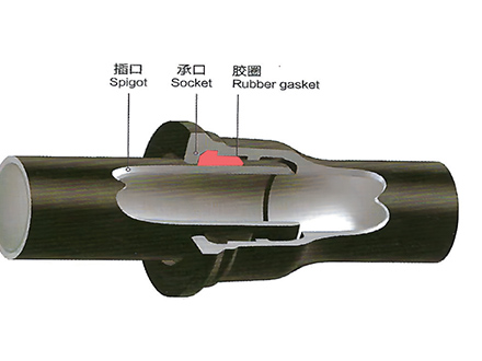 GT-type Joint Ductile Iron Pipe
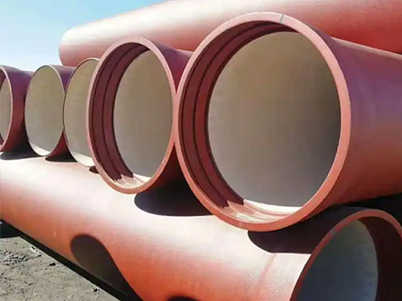
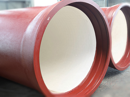 Sewage Pipe (Ductile Iron Sewage Pipe)
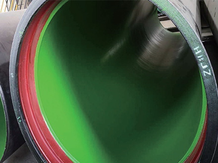 Special Coating Pipe (Ductile Iron Pipe with Special Coatings)