

Ductile Iron Pipe Wall Thickness by Pressure Class K8 K9 K10: Engineering Reference
Ductile Iron Pipe Wall Thickness by Pressure Class K8 K9 K10: Engineering Reference
Wall thickness is the critical parameter that determines ductile iron pipe's ability to withstand internal pressure, external loads, and handling stresses. Understanding pressure classes (K7 through K12), their relationship to wall thickness, and proper selection criteria is essential for safe and cost-effective pipeline design. This engineering reference provides comprehensive data, calculation methods, and practical selection guidelines.
ISO 2531 Pressure Class System
ISO 2531 defines pressure classes using the "K" system, where K values represent the allowable working pressure in bars with built-in surge allowance:
| Pressure Class | Working Pressure | Surge Allowance | Design Pressure | Typical Applications |
|---|---|---|---|---|
| K7 | 6 bar | 2 bar | 8 bar | Low-pressure irrigation, gravity systems |
| K8 | 8 bar | 4 bar | 12 bar | Rural water supply, small networks |
| K9 | 10 bar | 6 bar | 16 bar | Municipal distribution (standard) |
| K10 | 12 bar | 8 bar | 20 bar | High-pressure transmission, hilly terrain |
| K11 | 14 bar | 10 bar | 24 bar | Special high-pressure applications |
| K12 | 16 bar | 12 bar | 28 bar | Pump discharge, industrial |
Wall Thickness Calculation Formula
ISO 2531 specifies the following formula for minimum wall thickness:
e = minimum wall thickness (mm)
K = pressure class coefficient (7, 8, 9, 10, 11, 12)
DN = nominal diameter (mm)
Example Calculation - DN500 K9:
= 9 × (0.5 + 0.5)
= 9 × 1.0
= 9.0mm (rounded to 8.8mm in practice)
Complete Wall Thickness Table: DN80-DN2000
| DN | OD (mm) | Wall Thickness (mm) by Pressure Class | Weight K9 (kg/m) | |||
|---|---|---|---|---|---|---|
| K7 | K8 | K9 | K10 | |||
| DN80 | 98 | 3.0 | 3.5 | 4.0 | 4.5 | 14.8 |
| DN100 | 118 | 3.5 | 4.0 | 4.5 | 5.0 | 21.2 |
| DN150 | 170 | 4.0 | 4.5 | 5.0 | 5.6 | 32.5 |
| DN200 | 222 | 4.5 | 5.0 | 5.6 | 6.3 | 45.8 |
| DN250 | 274 | 5.0 | 5.6 | 6.3 | 7.0 | 62.4 |
| DN300 | 326 | 5.6 | 6.3 | 7.0 | 7.7 | 82.1 |
| DN350 | 378 | 6.0 | 6.8 | 7.5 | 8.3 | 104 |
| DN400 | 429 | 6.4 | 7.2 | 8.0 | 8.8 | 129 |
| DN450 | 480 | 6.8 | 7.6 | 8.4 | 9.3 | 155 |
| DN500 | 532 | 7.2 | 8.0 | 8.8 | 9.7 | 184 |
| DN600 | 635 | 8.0 | 8.8 | 9.6 | 10.6 | 245 |
| DN700 | 738 | 8.8 | 9.6 | 10.4 | 11.5 | 312 |
| DN800 | 842 | 9.6 | 10.4 | 11.2 | 12.4 | 385 |
| DN900 | 945 | 10.4 | 11.2 | 12.0 | 13.2 | 465 |
| DN1000 | 1048 | 11.2 | 12.0 | 12.8 | 14.0 | 552 |
| DN1200 | 1255 | 12.8 | 13.6 | 14.4 | 15.8 | 745 |
| DN1400 | 1462 | 14.4 | 15.2 | 16.0 | 17.5 | 965 |
| DN1600 | 1668 | 16.0 | 16.8 | 17.6 | 19.2 | 1215 |
| DN1800 | 1875 | 17.6 | 18.4 | 19.2 | 20.8 | 1495 |
| DN2000 | 2082 | 19.2 | 20.0 | 20.8 | 22.4 | 1805 |
Design Pressure vs Working Pressure
Understanding the difference is critical for proper pressure class selection:
Working Pressure (PFA)
Maximum continuous operating pressure the pipe can withstand indefinitely. This is the normal system pressure during steady-state operation.
Surge Pressure (P surge)
Temporary pressure increase caused by:
Pump startup or shutdown
Rapid valve closure
Sudden flow changes
Water hammer effects
Design Pressure (PDA)
The pipe must withstand design pressure without failure. K-classes include built-in surge allowance.
Surge Pressure Calculation
ΔP = surge pressure (Pa)
ρ = water density (1000 kg/m³)
a = wave speed (m/s) - typically 1000-1200 m/s for ductile iron
Δv = velocity change (m/s)
External Load Considerations
Wall thickness must also resist external loads from soil cover and traffic:
Ring Bending Stress
σ = bending stress (MPa)
M = bending moment per unit length (N·m/m)
e = wall thickness (m)
Minimum Thickness for External Loads
| Burial Depth | Traffic Load | Minimum Class | Notes |
|---|---|---|---|
| <1.5m | No traffic | K8 | Standard burial |
| 1.5-3.0m | Light traffic | K9 | Residential streets |
| 3.0-5.0m | Heavy traffic | K9-K10 | Main roads |
| >5.0m | Highway/airport | K10+ | Special design required |
Pressure Class Selection Guidelines
Municipal Water Distribution
Standard: K9 (covers 90% of applications)
Hilly terrain: K10 for lower elevations
High-rise supply: K10-K11 for downline sections
Transmission Mains
Gravity flow: K8-K9 (check external loads)
Pumped systems: K9-K10 (verify surge analysis)
Long distance: K10 recommended (surge margin)
Industrial Applications
Cooling water: K8-K9
Process water: K9-K10
Pump discharge: K11-K12 (high pressure)
Common Mistakes in Pressure Class Selection
While K9 works for most applications, using it universally can lead to failures in high-pressure zones or wasteful oversizing in low-pressure areas.
In hilly terrain, static pressure varies significantly. Bottom of hill may see 2-3× higher pressure than top.
Long transmission lines (>5km) can experience surge pressures 2-3× higher than short lines. Always perform surge analysis.
Before You Order Pressure-Class Pipes from China
Pressure class certification (K9, K10, PN16) requires verified testing equipment and quality control processes. Not all foundries have the same pressure class certifications. Through integrating production resources across qualified Chinese foundries, Tiegu delivers compliant and high-quality casting products to buyers worldwide while evaluating suppliers based on actual testing capabilities for specific pressure classes.
This ensures pressure ratings are backed by real production data, not just certificates.
Submit your pressure requirements to identify suppliers with valid certifications for your project.
Pressure Class Selection Checklist
☐ Working pressure determined from hydraulic analysis
☐ Surge analysis performed for lines >2km
☐ Design pressure calculated (PFA + surge)
☐ Elevation changes considered (static pressure variation)
☐ External loads verified (burial depth, traffic)
☐ Standard class selected (K9 most common)
☐ Special conditions noted (water hammer, deep burial)
☐ Hydrostatic test pressure confirmed (per ISO 2531)
Conclusion
Proper wall thickness and pressure class selection ensures safe, reliable ductile iron pipe performance over 50-100 year design life. K9 is suitable for most municipal applications, but always verify based on actual operating conditions, surge analysis, and external loads. When in doubt, consult ISO 2531 standards or request technical support from qualified suppliers.
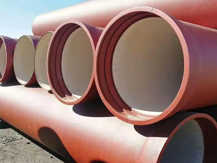
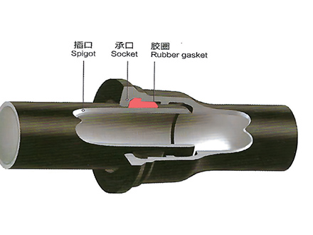 GT-type Joint Ductile Iron Pipe
 Sewage Pipe (Ductile Iron Sewage Pipe)
 Special Coating Pipe (Ductile Iron Pipe with Special Coatings)