

Ductile Iron Pipe Sizes and Dimensions: Complete Specification Guide for Water Infrastructure
Ductile Iron Pipe Sizes and Dimensions: Complete Specification Guide for Water Infrastructure
When specifying ductile iron pipe for water infrastructure projects, understanding the complete range of available sizes and dimensions is critical for proper system design, accurate cost estimation, and successful procurement. This comprehensive guide covers all standard ductile iron pipe sizes from DN80 to DN2000, along with their corresponding outside diameters, wall thicknesses by pressure class, and practical selection criteria based on real project experience.

Understanding Ductile Iron Pipe Sizing Standards
Ductile iron pipe sizing follows international standards that ensure compatibility across manufacturers and regions. The two primary standards used globally are:
ISO 2531: International Standard
ISO 2531 "Ductile iron pipes, fittings, accessories and their joints for water or gas applications" is the most widely adopted international standard. Key characteristics:
Pressure Classes: K7, K8, K9, K10, K11, K12 (K9 is most common for water applications)
Size Range: DN40 to DN2600
Standard Length: 6 meters for DN40-DN600, 6-7 meters for DN700+
Outside Diameter: Fixed per DN size, regardless of pressure class
Wall Thickness: Varies by pressure class, calculated per ISO formula
EN 545: European Standard
EN 545 "Ductile iron pipes, fittings, accessories and their joints for water pipelines - Requirements and test methods" is mandatory for European projects. Key differences from ISO 2531:
Pressure Classes: PN10, PN16, PN25, PN35, PN40 (PN16 most common)
Testing Requirements: More stringent hydrostatic and mechanical testing
Coating Standards: Specific requirements for zinc and cement mortar lining
Certification: Requires third-party certification (KIWA, DVGW, NSF)
DN (Diameter Nominal) System Explained
Both standards use the DN system, which represents the approximate internal diameter in millimeters. However, it's critical to understand that:
DN is NOT exact internal diameter - It's a nominal designation for compatibility
Outside diameter is constant for each DN size across all pressure classes
Internal diameter varies based on wall thickness (pressure class)
For example, DN300 pipe always has 326mm outside diameter, but internal diameter ranges from 312mm (K7) to 308mm (K10) due to wall thickness variation.
Complete Size Chart: DN80 to DN2000
The following comprehensive table shows standard ductile iron pipe dimensions across the full size range commonly used in water infrastructure projects:
| DN (mm) | Outside Diameter (mm) | Wall Thickness by Pressure Class (mm) | Standard Length (m) | Typical Application | |||
|---|---|---|---|---|---|---|---|
| K7 | K8 | K9 | K10 | ||||
| DN80 | 98 | 3.0 | 3.5 | 4.0 | 4.5 | 6 | Building connections |
| DN100 | 118 | 3.5 | 4.0 | 4.5 | 5.0 | 6 | Residential distribution |
| DN150 | 170 | 4.0 | 4.5 | 5.0 | 5.6 | 6 | Street mains |
| DN200 | 222 | 4.5 | 5.0 | 5.6 | 6.3 | 6 | Commercial areas |
| DN250 | 274 | 5.0 | 5.6 | 6.3 | 7.0 | 6 | Industrial zones |
| DN300 | 326 | 5.6 | 6.3 | 7.0 | 7.7 | 6 | District mains |
| DN350 | 378 | 6.0 | 6.8 | 7.5 | 8.3 | 6 | Transmission lines |
| DN400 | 429 | 6.4 | 7.2 | 8.0 | 8.8 | 6 | City trunk lines |
| DN450 | 480 | 6.8 | 7.6 | 8.4 | 9.3 | 6 | Regional supply |
| DN500 | 532 | 7.2 | 8.0 | 8.8 | 9.7 | 6 | Major transmission |
| DN600 | 635 | 8.0 | 8.8 | 9.6 | 10.6 | 6 | Primary mains |
| DN700 | 738 | 8.8 | 9.6 | 10.4 | 11.5 | 6 | Intercity transfer |
| DN800 | 842 | 9.6 | 10.4 | 11.2 | 12.4 | 6 | Large transmission |
| DN900 | 945 | 10.4 | 11.2 | 12.0 | 13.2 | 6 | Regional transfer |
| DN1000 | 1048 | 11.2 | 12.0 | 12.8 | 14.0 | 6 | Major projects |
| DN1200 | 1255 | 12.8 | 13.6 | 14.4 | 15.8 | 6 | Mega projects |
| DN1400 | 1462 | 14.4 | 15.2 | 16.0 | 17.5 | 6 | Special applications |
| DN1600 | 1668 | 16.0 | 16.8 | 17.6 | 19.2 | 6 | Special applications |
| DN1800 | 1875 | 17.6 | 18.4 | 19.2 | 20.8 | 6 | Special applications |
| DN2000 | 2082 | 19.2 | 20.0 | 20.8 | 22.4 | 6 | Special applications |
Wall Thickness and Pressure Class Relationship
ISO 2531 Wall Thickness Calculation
Wall thickness for each pressure class is calculated using the ISO formula:
e = minimum wall thickness (mm)
K = pressure class coefficient (K7=7, K8=8, K9=9, K10=10)
DN = nominal diameter (mm)
For example, DN500 K9 pipe:
Pressure Class Selection Guidelines
| Pressure Class | Working Pressure | Surge Pressure | Typical Applications |
|---|---|---|---|
| K7 | ≤6 bar | ≤8 bar | Low-pressure irrigation, gravity flow |
| K8 | ≤8 bar | ≤12 bar | Rural water supply, small networks |
| K9 | ≤10 bar | ≤16 bar | Municipal distribution (most common) |
| K10 | ≤12 bar | ≤20 bar | High-pressure transmission, hilly terrain |
Surge Pressure Considerations
Water hammer (surge pressure) can exceed working pressure by 50-100% during pump startup/shutdown or rapid valve closure. Always design for:
For K9 pipe with 10 bar working pressure, typical surge allowance is 6 bar, giving 16 bar design pressure. This is why K9 is suitable for most municipal applications despite 10 bar working pressure rating.
How to Select the Correct Pipe Size
Proper pipe sizing involves balancing hydraulic requirements, pressure ratings, and lifecycle costs. Follow this systematic approach:
Step 1: Calculate Design Flow Rate
Determine maximum expected water flow based on:
Population served: Current + projected (20-30 year horizon)
Per capita consumption: Typically 150-300 liters/person/day
Peak factor: 1.5-2.5× average daily consumption
Fire flow requirements: Local fire code specifications
Step 2: Determine Allowable Velocity
Water velocity affects friction loss and pipe wear:
Water distribution: 0.5-1.5 m/s (optimal: 1.0 m/s)
Transmission mains: 1.0-2.0 m/s (optimal: 1.5 m/s)
Maximum velocity: 2.5 m/s (avoid exceeding to prevent erosion)
D = internal diameter (m)
Q = flow rate (m³/s)
v = velocity (m/s)
Step 3: Calculate Pressure Loss
Use Hazen-Williams equation for water flow:
hf = friction head loss (m)
L = pipe length (m)
Q = flow rate (m³/s)
C = roughness coefficient (140-150 for ductile iron)
D = internal diameter (m)
Step 4: Evaluate Lifecycle Cost
Larger diameter means higher material cost but lower pumping cost. Perform net present value (NPV) analysis over 50-year project life:
Material cost: Pipe, fittings, installation (increases with diameter)
Pumping cost: Energy for friction loss (decreases with diameter)
Maintenance cost: Similar across reasonable size range
Rule of thumb: For transmission mains >5km, upsizing one diameter often pays back within 10 years through reduced pumping costs.
Common Sizing Mistakes to Avoid
Based on project experience, here are frequent errors in ductile iron pipe specification and their consequences:
Mistake 1: Confusing DN with Actual Internal Diameter
Problem: DN300 does NOT mean 300mm internal diameter. Actual ID varies from 308-315mm depending on pressure class.
Consequence: Hydraulic calculations based on wrong ID lead to undersized pipe and higher-than-expected friction loss.
Solution: Always use actual internal diameter from manufacturer data sheets for hydraulic calculations.
Mistake 2: Underestimating Surge Pressure
Problem: Designing for working pressure only, ignoring water hammer effects.
Consequence: Pipe bursts during pump shutdown or rapid valve closure, especially in long transmission lines.
Solution: Perform surge analysis using software (HAMMER, Surge 2000) or conservative rule-of-thumb (add 50-100% of working pressure).
Mistake 3: Ignoring External Loads
Problem: Selecting K9 for all applications without considering burial depth and traffic loads.
Consequence: Pipe deformation under heavy loads (highways, airports), leading to joint leaks and structural failure.
Solution: For burial depth >3m or under heavy traffic, verify ring bending stress per ISO 2531 Annex B. Consider K10 or special thickness class.
Mistake 4: Oversizing Without Justification
Problem: "Bigger is safer" mentality leads to excessive diameters.
Consequence: 20-40% higher material cost, larger trench excavation, more expensive fittings, without proportional benefit.
Solution: Base sizing on hydraulic calculations and lifecycle cost analysis, not intuition.
Dimensional Tolerances per ISO 2531
Understanding acceptable tolerances is essential for quality inspection during procurement:
| Parameter | Standard Tolerance | Inspection Method | Acceptance Criteria |
|---|---|---|---|
| Outside Diameter | ±1% of DN | Circumferential tape measurement | Must be within ±1% at all points |
| Wall Thickness | -1.3mm minimum | Ultrasonic thickness gauge | No reading below (nominal - 1.3mm) |
| Length | ±50mm for 6m pipes | Tape measure or laser distance meter | Within ±50mm of specified length |
| Straightness | ≤0.125% of length | String line or laser alignment | Maximum deviation ≤7.5mm for 6m pipe |
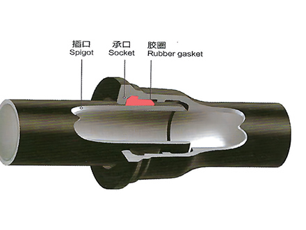
| Spigot Diameter | Per ISO 2531 Table 8 | Caliper or micrometer | Within specified range for joint type |
| Socket Depth | ±5mm | Depth gauge | Ensures proper joint engagement |
| Cement Lining Thickness | ≥3mm (DN40-DN300) ≥4mm (DN350+) | Core sample or magnetic gauge | Average ≥ specified, no point<80% of spec |
| Zinc Coating Weight | ≥200g/m² | X-ray fluorescence or chemical test | Average ≥200g/m² |
Special Sizes and Custom Options
While standard sizes cover most applications, some projects require non-standard options:
Small Diameter (DN40-DN65)
Available from select manufacturers for building service connections and branch lines. Key considerations:
Limited suppliers: Not all Chinese foundries produce below DN80
Higher unit cost: Smaller production volumes
Joint types: Usually compression or push-on, rarely flanged
Lead time: May require special production run (60-90 days)
Large Diameter (DN2200-DN2600)
For major water transmission projects. Critical considerations:
Production capacity: Only 5-8 Chinese foundries can produce DN2000+
Transportation: Requires special permits and route survey
Installation: Heavy equipment needed (50+ ton cranes)
Lead time: 120-150 days typical
Price premium: 30-50% higher than DN1600 per meter
Non-Standard Wall Thickness
Engineered solutions for extreme conditions:
Special thickness class: K11, K12 for ultra-high pressure
Custom thickness: Between standard K-classes
Variable thickness: Different thickness along pipe length for specific load conditions
MOQ: Typically 500+ meters for custom thickness
Special Lengths
Custom cutting to reduce field joints:
5.5m lengths: For restricted access sites
7m lengths: For large diameter to reduce joint count
Specific lengths: Cut to match structure spacing (bridge crossings, etc.)
Cost impact: Minimal for standard sizes, significant for large diameter
Working with Chinese Foundries for Pipe Dimensions
Dimensional consistency across production batches directly affects installation efficiency and joint integrity in water infrastructure projects. By integrating production capacity across qualified Chinese foundries, Tiegu delivers compliant and high-quality casting products to buyers worldwide with visibility into actual supplier performance beyond certificates.
This ensures dimensional accuracy and coating quality match project specifications across the entire order volume.
Submit your drawings or pipe dimension requirements for technical evaluation and supplier matching.
Procurement Checklist
☐ Outside diameter confirmed for fitting compatibility with existing system
☐ Wall thickness meets external load requirements (burial depth, traffic)
☐ Standard length (6m) or special length clearly specified
☐ Dimensional tolerances align with project quality standards (ISO 2531 or EN 545)
☐ Manufacturer capability confirmed for required size range (especially DN1400+)
☐ Lead time acceptable for project schedule (30-60 days standard, 90-120 days for large diameter)
☐ Third-party inspection arranged (SGS, BV, TUV for critical projects)
☐ Certification requirements specified (ISO 2531, EN 545, NSF, KIWA, DVGW)
Conclusion
Understanding ductile iron pipe sizes and dimensions is fundamental to successful water infrastructure procurement. From DN80 service connections to DN2000 transmission mains, each size has specific dimensional characteristics that affect system performance, installation requirements, and lifecycle cost.
Key takeaways for procurement managers:
DN is nominal, not exact - Always verify actual dimensions from manufacturer data sheets
Outside diameter is constant - Fittings are interchangeable across pressure classes for same DN
Pressure class affects wall thickness - K9 is standard, but verify surge and external load requirements
Size selection requires analysis - Balance hydraulic performance with lifecycle cost
Tolerances matter - Specify inspection criteria in purchase order
Large diameter needs planning - Confirm supplier capability and lead time early
For specific project requirements or questions about available sizes from Chinese manufacturers, request detailed technical specifications early in the procurement process. This confirms availability, validates lead times, and ensures your ductile iron pipe system delivers reliable performance for the expected 50-100 year design life.
 GT-type Joint Ductile Iron Pipe
 Sewage Pipe (Ductile Iron Sewage Pipe)
 Special Coating Pipe (Ductile Iron Pipe with Special Coatings)