

Ductile Iron Pipe Joint Types: TYTON vs RESTRAINED vs FLANGED Complete Guide
Ductile Iron Pipe Joint Types: TYTON vs RESTRAINED vs FLANGED Complete Guide
Joint selection is one of the most critical decisions in ductile iron pipeline design. The wrong joint type can lead to leaks, joint separation, costly repairs, or even catastrophic pipeline failure. Understanding the differences between TYTON (push-on), restrained, flanged, and mechanical joints—and knowing when to use each—is essential for engineers, contractors, and procurement managers. This comprehensive guide covers joint types, applications, installation procedures, and selection criteria based on 50+ years of industry experience.
Quick Reference: TYTON joints are used for 90% of straight pipeline runs. Restrained joints are required at bends, tees, valves, and other fittings where thrust forces occur. Flanged joints connect to valves, pumps, and equipment. Mechanical joints are used for repairs and special connections.

Joint Type Overview
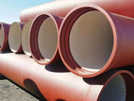
1. TYTON Push-On Joint
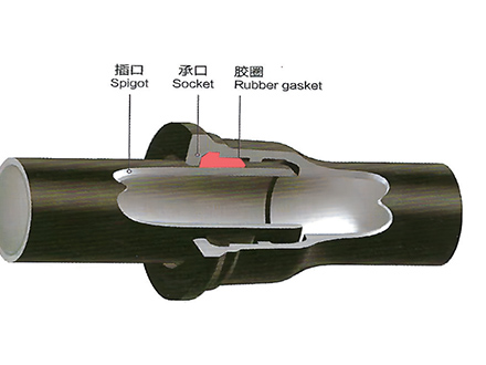
Also Known As: Push-on joint, spigot-and-socket joint, bell-and-spigot joint
Standard: ISO 2531, EN 545, AWWA C151
Description: The TYTON joint is a push-on mechanical joint that uses a single rubber gasket seated in the bell (socket) to create a pressure-tight seal. The spigot (plain end) is inserted into the bell, compressing the gasket to form the seal.
Key Components:
Bell (Socket): Enlarged end of pipe with gasket groove
Spigot (Plain End): Standard end that inserts into bell
Rubber Gasket: EPDM or SBR compound, provides sealing
Lubricant: Non-petroleum based, reduces insertion friction
Advantages:
✅ Fastest installation (30-60 seconds per joint)
✅ No special tools required (lever or excavator bucket)
✅ Allows deflection (3-5° depending on size)
✅ Accommodates thermal expansion/contraction
✅ Most cost-effective joint type
✅ Proven reliability (50+ years of service)
Limitations:
❌ Not restrained (requires thrust blocks at fittings)
❌ Cannot be used in above-ground applications without restraint
❌ Gasket can be damaged during installation if not careful
Pressure Rating: Same as pipe pressure class (K9, PN16, etc.)
Temperature Range: -20°C to +50°C (standard EPDM gasket)
2. Restrained Joint
Also Known As: Locking joint, thrust-resistant joint, anchored joint
Standard: ISO 2531, EN 545, AWWA C151
Description: Restrained joints incorporate a locking mechanism that prevents joint separation under thrust forces while maintaining the push-on seal. Various designs exist: wedge-action locks, grip rings, or bolted restraint glands.
Key Components:
Base Joint: TYTON-style push-on seal
Restraint Mechanism: Wedges, grip rings, or bolts
Gland/Gripper: Transfers thrust load to pipe wall
Advantages:
✅ Eliminates need for thrust blocks in most applications
✅ Resists axial separation forces
✅ Maintains pressure-tight seal under thrust
✅ Faster installation than concrete thrust blocks
✅ Suitable for horizontal directional drilling (HDD)
Limitations:
❌ 2-3× more expensive than TYTON joints
❌ Requires proper installation torque/procedure
❌ Limited deflection compared to TYTON
❌ Cannot be disassembled easily once installed
Pressure Rating: Same as pipe pressure class
Thrust Capacity: Varies by size and manufacturer (typically 50-200 kN)
3. Flanged Joint
Also Known As: Flange connection, bolted flange
Standard: ISO 2531, EN 1092, ASME B16.1, AWWA C110
Description: Flanged joints use machined flanges bolted together with a gasket between flange faces. Used primarily for connections to valves, pumps, tanks, and other equipment with flanged ends.
Key Components:
Flange: Cast or welded to pipe end
Bolts/Nuts: High-strength steel, corrosion-protected
Gasket: Rubber, PTFE, or spiral-wound (depending on service)
Washers: Hardened steel, distribute bolt load
Advantages:
✅ Rigid connection (no movement)
✅ Easy disassembly for maintenance
✅ Compatible with standard flanged equipment
✅ Suitable for above-ground installations
✅ High pressure capability (PN25, PN40 available)
Limitations:
❌ Bulky and heavy
❌ Requires precise alignment
❌ Bolt tightening requires torque wrench
❌ Not suitable for buried applications without protection
❌ Most expensive joint type
Pressure Rating: PN10, PN16, PN25, PN40 (depends on flange rating)
Temperature Range: Depends on gasket material (typically -20°C to +100°C)
4. Mechanical Joint (MJ)
Also Known As: Dresser coupling, Victaulic coupling, flexible coupling
Standard: AWWA C111, ISO 2531
Description: Mechanical joints use a gland and follower ring compressed by bolts to create a seal. Often used for repairs, valve connections, or transitions between different pipe materials.
Key Components:
Gland: Cast iron or ductile iron housing
Follower Ring: Compresses gasket
Gasket: Rubber, provides seal
Bolts/Nuts: T-bolts or standard hex bolts
Advantages:
✅ Accommodates some pipe OD variation
✅ Allows limited deflection and movement
✅ Easy to install and remove
✅ Useful for repairs and emergency work
✅ Connects different pipe materials
Limitations:
❌ Bulkier than push-on joints
❌ Requires bolt tightening (slower than TYTON)
❌ Not as widely used for new installations
❌ Higher cost than TYTON
Pressure Rating: Typically PN16 (some designs up to PN25)
Joint Selection by Application
Buried Water Distribution Mains
| Application | Recommended Joint | Notes |
|---|---|---|
| Straight runs | TYTON push-on | Standard choice, 90% of pipeline |
| Horizontal bends (≤11.25°) | TYTON + thrust block | Small bends can use thrust blocks |
| Horizontal bends (>11.25°) | Restrained joint | Eliminates large thrust blocks |
| Vertical bends | Restrained joint | Always use restrained for vertical |
| Tees and crosses | Restrained joint | On all branches and run |
| Valve connections | Flanged or MJ | Depends on valve end type |
| Dead ends | Restrained + cap | Or thrust block behind cap |
Transmission Mains
| Application | Recommended Joint | Notes |
|---|---|---|
| Straight runs (buried) | TYTON push-on | Standard |
| River crossings | Restrained joint | Entire crossing section |
| Horizontal directional drilling | Restrained joint | Mandatory for HDD pullback |
| Above-ground sections | Flanged or restrained | With proper support |
| Pump station piping | Flanged | Standard for equipment connection |
Industrial Applications
| Application | Recommended Joint | Notes |
|---|---|---|
| Plant piping (above ground) | Flanged | Easy maintenance access |
| Cooling water lines | TYTON (buried) / Flanged (above) | Depends on location |
| Slurry pipelines | Restrained + special lining | High wear applications |
| Fire protection | TYTON or mechanical | Per NFPA requirements |
| Process connections | Flanged | Equipment compatibility |
When to Use Restrained Joints: Detailed Guidelines
Restrained joints are required wherever thrust forces occur. Thrust is the axial force generated by internal pressure acting on changes in pipeline direction or cross-section.
Thrust Force Calculation
T = Thrust force (kN)
P = Design pressure (bar) × 0.1 = MPa
A = Cross-sectional area based on pipe OD (m²)
Thrust Forces at Fittings (K9/PN16, 10 bar)
| DN | 90° Bend | 45° Bend | 22.5° Bend | 11.25° Bend | Tee (Branch) | Dead End |
|---|---|---|---|---|---|---|
| DN200 | 49 kN | 26 kN | 14 kN | 7 kN | 35 kN | 49 kN |
| DN300 | 110 kN | 58 kN | 31 kN | 16 kN | 78 kN | 110 kN |
| DN400 | 195 kN | 103 kN | 55 kN | 28 kN | 138 kN | 195 kN |
| DN500 | 305 kN | 161 kN | 86 kN | 44 kN | 216 kN | 305 kN |
| DN600 | 440 kN | 232 kN | 124 kN | 63 kN | 311 kN | 440 kN |
| DN800 | 780 kN | 412 kN | 220 kN | 112 kN | 552 kN | 780 kN |
Restraint Length Calculation
When using restrained joints, calculate required restraint length on each side of fitting:
Lr = Required restraint length (m)
SF = Safety factor (typically 1.5)
T = Thrust force (kN)
fs = Soil friction resistance (kN/m)
fb = Passive soil resistance (kN/m)
Typical Restraint Lengths (DN300-DN600, average soil):
90° bend: 6-10 restrained joints per side
45° bend: 4-6 restrained joints per side
Tee: 4-8 restrained joints per side
Dead end: 6-10 restrained joints
Installation Procedures
TYTON Joint Installation
Restrained Joint Installation
Flanged Joint Installation
Joint Type Comparison Summary
| Criteria | TYTON | Restrained | Flanged | Mechanical |
|---|---|---|---|---|
| Installation Speed | Fastest (30-60 sec) | Fast (2-3 min) | Slow (10-15 min) | Medium (5-8 min) |
| Cost | Lowest (baseline) | 2-3× TYTON | 5-8× TYTON | 3-4× TYTON |
| Thrust Resistance | None | Full | Full | Limited |
| Deflection | 3-5° | 1-2° | None | 2-3° |
| Disassembly | Difficult | Very difficult | Easy | Easy |
| Buried Service | Excellent | Excellent | Not recommended | Good |
| Above Ground | No | Yes (with support) | Excellent | Yes |
| Applications | 90% of pipeline | Fittings, HDD | Equipment, valves | Repairs, transitions |
Coordinating Joint Types Across Multiple Suppliers
Joint compatibility becomes critical when sourcing pipes and fittings from different foundries. TYTON dimensions follow ISO 2531 standards, but restrained joint systems vary by manufacturer. Through integrating production resources across qualified Chinese foundries, Tiegu delivers compliant and high-quality casting products to buyers worldwide while ensuring joint compatibility across multi-supplier orders.
This prevents installation delays caused by incompatible joint dimensions or gasket mismatches.
Submit your pipeline layout to verify joint compatibility before placing orders with multiple suppliers.
Joint Selection Checklist
☐ Application identified (buried, above-ground, equipment connection)
☐ Thrust analysis completed (calculate forces at all fittings)
☐ Joint type selected (TYTON for straight, restrained for thrust, flanged for equipment)
☐ Restraint length calculated (for restrained joints)
☐ Installation procedure reviewed (contractor trained on proper methods)
☐ Gasket material verified (EPDM for potable water, NBR for hydrocarbons)
☐ Bolt torque specifications confirmed (for restrained and flanged joints)
☐ Inspection criteria defined (visual, torque check, pressure test)
Conclusion
Proper joint selection is critical for ductile iron pipeline performance and longevity. TYTON push-on joints are the workhorse for straight buried runs, offering fast installation and proven reliability. Restrained joints eliminate thrust blocks at fittings and are mandatory for HDD installations. Flanged joints provide rigid, demountable connections for equipment and above-ground piping.
Key selection principles:
Use TYTON for: 90% of buried straight runs
Use Restrained for: Bends, tees, dead ends, HDD, river crossings
Use Flanged for: Valve/pump connections, above-ground piping, equipment
Use Mechanical for: Repairs, transitions, special connections
Always follow manufacturer installation instructions and verify joint integrity through proper inspection and testing. The cost of joint failure (leaks, separation, service interruption) far exceeds any savings from improper joint selection or installation.
 GT-type Joint Ductile Iron Pipe
 Sewage Pipe (Ductile Iron Sewage Pipe)
 Special Coating Pipe (Ductile Iron Pipe with Special Coatings)