
Thrust Restraint Design for Ductile Iron Pipe: Engineering Guide
Thrust restraint is critical for ductile iron pipeline integrity at fittings, valves, and changes in direction. Internal pressure creates unbalanced forces that can separate joints, displace fittings, and cause catastrophic failure if not properly restrained. Engineers must calculate thrust forces, select appropriate restraint methods (thrust blocks, restrained joints, or anchors), and design systems to safely transfer forces to surrounding soil. This comprehensive guide covers thrust force calculations, restraint design methods, installation requirements, and common mistakes.

Thrust Force Fundamentals
What Causes Thrust?
Thrust forces occur when internal pressure acts on an unbalanced area, such as:
Bends: Pressure pushes against change in direction
Tees: Pressure pushes against branch outlet
Dead ends (caps): Pressure pushes against end cap
Valves: Pressure pushes against closed valve disc
Reducers: Pressure acts on area difference
Thrust Force Calculation
T = 2 × P × A × sin(θ/2)
T = Thrust force (kN)
P = Internal pressure (bar) × 100 (convert to kPa)
A = Pipe cross-sectional area (m²) = π × D² / 4
θ = Bend angle (degrees)
D = Inside diameter (m)
Thrust Forces at 90° Bends (Simplified)
| DN | OD (mm) | Area (m²) | Thrust @ 10 bar | Thrust @ 16 bar | Thrust @ 25 bar |
|---|---|---|---|---|---|
| DN100 | 118 | 0.0109 | 15.4 kN (1.6 tons) | 24.7 kN (2.5 tons) | 38.6 kN (3.9 tons) |
| DN200 | 222 | 0.0387 | 54.7 kN (5.6 tons) | 87.5 kN (8.9 tons) | 136.8 kN (13.9 tons) |
| DN300 | 326 | 0.0835 | 118.1 kN (12.0 tons) | 189.0 kN (19.3 tons) | 295.3 kN (30.1 tons) |
| DN400 | 429 | 0.1445 | 204.4 kN (20.8 tons) | 327.0 kN (33.3 tons) | 511.0 kN (52.1 tons) |
| DN500 | 532 | 0.2223 | 314.4 kN (32.0 tons) | 503.0 kN (51.3 tons) | 786.0 kN (80.1 tons) |
| DN600 | 635 | 0.3167 | 447.9 kN (45.7 tons) | 716.6 kN (73.1 tons) | 1119.7 kN (114.2 tons) |
Restraint Methods
Method 1: Concrete Thrust Blocks
| Advantage | Limitation |
|---|---|
| Low material cost | Requires undisturbed soil |
| Simple design | Large excavation required |
| Permanent | Cannot be removed for maintenance |
| Works for all DN | Curing time delays testing |
Thrust Block Sizing (Simplified)
A = T / (S × F)
A = Required bearing area (m²)
T = Thrust force (kN)
S = Soil bearing capacity (kPa)
F = Safety factor (1.5 minimum)
Soil Bearing Capacities
| Soil Type | Bearing Capacity | Notes |
|---|---|---|
| Hard rock | 400-800 kPa | Excellent, rarely needs thrust block |
| Dense gravel | 200-400 kPa | Good for thrust blocks |
| Dense sand | 100-200 kPa | Adequate for most applications |
| Firm clay | 75-150 kPa | May require larger blocks |
| Soft clay | 25-75 kPa | Poor, consider restrained joints |
| Loose sand/fill | <25 kPa | Unsuitable, use restrained joints |
Method 2: Restrained Joints
| Advantage | Limitation |
|---|---|
| No concrete required | Higher material cost |
| Fast installation | Requires proper installation length |
| Works in poor soil | Must be installed correctly |
| Allows maintenance access | Limited to certain DN ranges |
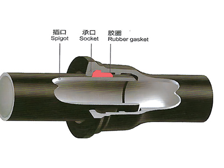
Restrained Joint Types
| Type | Mechanism | DN Range | Pressure Rating |
|---|---|---|---|
| Mechanical grip | Wedging action on pipe OD | DN80-600 | PN16-PN25 |
| Welded restraint | Steel ring welded to pipe | DN200-1000 | PN16-PN40 |
| Threaded rod | Rods connect bell to adjacent pipe | DN100-400 | PN16 |
| Locking segment | Segments lock into groove | DN80-300 | PN16-PN25 |
Method 3: Anchor Blocks
| Application | Design Requirement |
|---|---|
| Above-ground piping | Structural steel or concrete anchor |
| Bridge crossings | Engineered anchor system |
| Penstocks | Reinforced concrete anchor |
| Pump discharge | Mass concrete with rebar |
Restraint Requirements by Fitting Type
90° Bends
| DN | Restraint Length (each leg) | Method |
|---|---|---|
| DN80-200 | 3-5m | Restrained joints or thrust block |
| DN250-400 | 5-8m | Restrained joints preferred |
| DN450-600 | 8-12m | Restrained joints or engineered anchor |
| DN700+ | Engineered design | Structural engineer required |
Tees
| Tee Type | Restraint Location | Notes |
|---|---|---|
| Equal tee | All three legs | Thrust on branch and both run ends |
| Reducing tee | All three legs | Calculate thrust for each diameter |
| Lateral tee | Branch and upstream run | Downstream may not need restraint |
Dead Ends (Caps)
| DN | Thrust Force @ 16 bar | Restraint Method |
|---|---|---|
| DN100 | 17.6 kN (1.8 tons) | Thrust block or restrained joint |
| DN200 | 62.5 kN (6.4 tons) | Thrust block or restrained joint |
| DN300 | 135.0 kN (13.8 tons) | Restrained joint preferred |
| DN400 | 233.6 kN (23.8 tons) | Restrained joint or anchor |
| DN500 | 359.3 kN (36.6 tons) | Engineered anchor |
Valves
| Valve Type | Restraint Requirement |
|---|---|
| Gate valve (closed) | Restrain both sides |
| Butterfly valve (closed) | Restrain both sides |
| Check valve | Restrain downstream side |
| Air release valve | Restrain connection point |
Installation Requirements
Thrust Block Installation
Bear against undisturbed soil (not backfill)
Concrete strength: minimum 20 MPa (28-day)
Place fitting before pouring concrete
Allow 7 days curing before pressure testing
Use formwork for proper shape
Restrained Joint Installation
Install per manufacturer instructions
Verify proper engagement (mark on pipe)
Torque bolts to specified value
Maintain minimum restraint length
Do not deflect restrained joints beyond limits
Common Design Mistakes
Mistake 1: Thrust Block Against Backfill
Problem: Pouring thrust block against loose backfill instead of undisturbed soil.
Consequence: Block moves under load, joint separates, catastrophic failure.
Solution: Excavate to undisturbed soil. If not possible, use restrained joints instead.
Mistake 2: Insufficient Restraint Length
Problem: Not installing enough restrained joints to develop full resistance.
Consequence: Joints pull apart, fitting displaces.
Solution: Calculate required restraint length. Install minimum 3-5 restrained joints per leg.
Mistake 3: Restraining Only One Side
Problem: Restraining only one leg of a bend or tee.
Consequence: Unrestrained side fails, fitting rotates.
Solution: Restrain all legs that experience thrust force.
Mistake 4: Ignoring Test Pressure
Problem: Designing for working pressure, not test pressure.
Consequence: Restraint fails during hydrostatic testing.
Solution: Design for 1.5 × working pressure (test pressure).
Supply Chain Perspective
Fitting and Restraint System Coordination
Fittings and restraint systems must be compatible. Some manufacturers offer integrated restrained fittings; others require separate restraint devices. Lead times vary - standard fittings may stock in 2-4 weeks; restrained fittings may require 8-12 weeks. Tiegu integrates production capacity across qualified Chinese foundries, delivering compliant and high-quality casting products to buyers worldwide while coordinating fitting production with restraint system availability to ensure complete, compatible systems arrive on schedule.
This prevents project delays from mismatched components or missing restraint devices.
Submit your project specifications and fitting requirements to confirm compatibility and delivery schedules.
Design Checklist
☐ Thrust forces calculated (all fittings, valves, dead ends)
☐ Restraint method selected (thrust block, restrained joint, or anchor)
☐ Soil conditions verified (bearing capacity for thrust blocks)
☐ Restraint length calculated (for restrained joint systems)
☐ Test pressure considered (design for 1.5 × working pressure)
☐ All fittings identified (90° bends, tees, caps, valves)
☐ Installation sequence planned (fitting placement before concrete)
☐ Inspection points defined (verify restraint before backfill)
Conclusion
Thrust restraint is critical for pipeline safety. Unrestrained thrust forces can separate joints, displace fittings, and cause catastrophic failure. Engineers must calculate thrust forces, select appropriate restraint methods, and verify installation quality.
Key points:
Calculate thrust: Use T = 2 × P × A × sin(θ/2) for bends
Restrain all fittings: Bends, tees, caps, valves
Select method: Thrust blocks (good soil), restrained joints (poor soil)
Design for test pressure: 1.5 × working pressure
Verify installation: Inspect before backfill
For complex systems or high pressures, consult a structural engineer. Proper thrust restraint design prevents costly failures and ensures pipeline integrity.
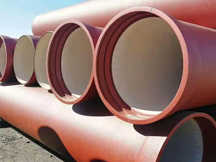
 GT-type Joint Ductile Iron Pipe
 Sewage Pipe (Ductile Iron Sewage Pipe)
 Special Coating Pipe (Ductile Iron Pipe with Special Coatings)