
How to Prevent Stray Current Corrosion in Pipelines? Complete Protection Guide
How to Prevent Stray Current Corrosion in Pipelines? Complete Protection Guide

, flows through pipe metal, and exits at discharge area (anodic, severe corrosion)")
Table of Contents
What Is Stray Current Corrosion and Why Is It Dangerous?
How Do Stray Currents Cause Rapid Pipe Corrosion?
What Are the Common Sources of Stray Currents?
How to Detect Stray Current Interference on Pipelines?
How Does Drainage Bonding Prevent Stray Current Corrosion?
Can Coatings Reduce Stray Current Pickup?
How to Coordinate Cathodic Protection Systems to Avoid Interference?
What Special Measures Protect Pipelines Near Railways?
How to Specify Stray Current Protection for Your Pipeline?
What Is Stray Current Corrosion and Why Is It Dangerous?
Stray current corrosion occurs when external direct current (DC) electrical sources force current to flow through buried pipelines. Unlike natural electrochemical corrosion driven by millivolt-level potential differences, stray currents operate at volt-level potentials — causing metal loss rates that can penetrate pipe walls within months rather than decades.
The term "stray current" refers to DC current that has escaped its intended circuit (such as railway traction systems or cathodic protection installations) and is flowing through unintended paths — including water pipes, gas pipelines, cable sheaths, or reinforcement steel in concrete.
Key characteristics that make stray current corrosion uniquely dangerous:
Extreme corrosion rates: 10-1000x faster than natural corrosion — failure in months vs. decades
Highly localized attack: Concentrated at current discharge points (often coating defects or joints)
Time-variable intensity: Correlates with external source operation (train schedules, welding operations, CP system cycling)
Difficult to predict: Depends on dynamic factors (railway load, soil moisture, coating degradation)
Can affect protected pipes: Even cathodically protected pipelines can suffer stray current damage if interference exceeds CP system capacity
How Do Stray Currents Cause Rapid Pipe Corrosion?
Understanding the mechanism is essential for selecting appropriate mitigation measures:
Current Flow Pattern
Stray current follows the path of least resistance:
Current pickup area: Stray current enters the pipe from soil at locations where pipe potential is more negative than surrounding soil. At this area, the pipe acts as a cathode — it is protected from corrosion (electrons flow into the pipe).
Longitudinal flow: Current flows through the pipe metal (low resistance path) along the pipeline route.
Current discharge area: Current leaves the pipe and returns to soil at locations where pipe potential is more positive than soil. At this area, the pipe acts as an anode — severe corrosion occurs (electrons flow out of the pipe).
At discharge area (anode): Fe → Fe²⁺ + 2e⁻ (iron dissolves)
Electrons flow through pipe metal to external circuit
Metal loss rate: 1 A DC = 9.13 kg iron/year = 1.16 mm³/s
Faraday's Law Application
The metal loss rate from stray current corrosion is precisely predictable using Faraday's law of electrolysis:
| Metal | Metal Loss per 1 A·year | Volume Loss per 1 A |
|---|---|---|
| Iron (Fe) | 9.13 kg/year | 1.16 mm³/s |
| Steel (Fe-C alloy) | ~9 kg/year | ~1.15 mm³/s |
| Zinc (Zn) | 10.9 kg/year | 1.53 mm³/s |
| Copper (Cu) | 10.4 kg/year | 1.16 mm³/s |
For ductile iron pipes, this means:
1 A stray current: Removes 9.13 kg iron/year — equivalent to ~1,160 mm³ of metal per second
10 A stray current: Removes 91.3 kg/year — can penetrate 10mm wall pipe in 1-2 years at concentrated discharge point
100 A stray current: Removes 913 kg/year — catastrophic failure within months
Typical DC transit systems leak 10-50% of traction current into soil — for a 1000A train, this means 100-500A of stray current seeking return paths through buried utilities.
What Are the Common Sources of Stray Currents?
Identifying the source is the first step in mitigation — different sources require different countermeasures:
1. DC Transit Systems (Most Common)
Examples: Electric railways, subways, light rail, trolley buses, tramways
Mechanism: Traction power substations supply DC current (600-1500V) to trains via overhead catenary or third rail. Current returns to substation through running rails. However, rails are not perfectly insulated from ground — current leaks into soil and seeks alternative low-resistance paths through buried pipes.
Characteristics:
Corrosion rate varies with train schedule (peak hours = higher corrosion)
Pipe-to-soil potential shifts correlate with train position (measurable ±5-20V)
Damage concentrated near railway corridors (typically within 100-500m)
Current direction reverses if train position changes relative to pipe crossing
2. Cathodic Protection Systems
Examples: Impressed current CP systems on adjacent pipelines, tank farms, marine terminals
Mechanism: CP rectifiers force current from anode groundbed through soil to protected pipeline. If another pipeline is nearby, some CP current may flow through the unprotected pipe before returning to soil — creating interference.
Characteristics:
Potential shifts synchronized with CP system operation (continuous or interrupted)
Interference radius depends on soil resistivity and CP current output (typically 50-300m)
Can be mitigated by CP system coordination between pipeline operators
3. Welding Operations
Examples: DC arc welding using earth grounds, electroslag welding, resistance welding
Mechanism: Welding machines use workpiece as current return path. If ground clamp is poorly connected, current seeks alternative paths through nearby buried structures.
Characteristics:
Temporary but severe — damage can occur during single welding session
Often overlooked because welding is intermittent
Common at construction sites, shipyards, fabrication facilities
4. High-Voltage DC Transmission (HVDC)
Examples: HVDC ground electrodes for power transmission, HVDC converter stations
Mechanism: HVDC systems use earth as return path during monopolar operation or unbalanced conditions. Ground electrodes inject hundreds to thousands of amperes into soil, creating large potential gradients.
Characteristics:
Very large interference zone (kilometers from electrode)
Long-duration events (hours to days during maintenance or faults)
Requires specialized mitigation (often regulated by power utility standards)
5. Mining and Industrial Operations
Examples: Electrorefining, electrowinning, aluminum smelting, chlor-alkali plants
Mechanism: Industrial electrolytic processes use high DC currents (thousands of amperes). Current leakage from cells, busbars, or ground faults creates stray current fields.
Characteristics:
Continuous operation (24/7 for process plants)
High current density (severe corrosion potential)
Often combined with chemical contamination (accelerated corrosion)
How to Detect Stray Current Interference on Pipelines?
Early detection is critical — waiting for leaks or failures is too late. Implement systematic monitoring:
Method 1: Pipe-to-Soil Potential Monitoring
Install permanent reference electrodes (Cu/CuSO₄ or Ag/AgCl) at strategic locations along pipeline. Measure pipe-to-soil potential continuously or at regular intervals.
Indicators of stray current:
Potential shifts > ±100 mV: Natural corrosion potentials are stable (-0.5 to -0.8V vs. Cu/CuSO₄). Stray currents cause dynamic shifts.
Positive shifts (anodic): Potential becomes less negative — indicates current discharge (corrosion area)
Negative shifts (cathodic): Potential becomes more negative — indicates current pickup (protected area)
Time correlation: Potential fluctuations synchronized with external source operation (train schedules, CP cycling)
Method 2: Current Flow Measurement
Measure actual current flowing through pipe using clamp-on ammeters or installed current meters:
Clamp-on DC ammeter: Non-invasive measurement around exposed pipe sections (valve stations, above-ground crossings)
Current shunts: Install permanent shunts at insulating joints for continuous monitoring
Current direction: Identify flow direction to locate pickup vs. discharge areas
Method 3: Close-Interval Survey (CIS)
Walk pipeline route with reference electrode, measuring pipe-to-soil potential at 1-5m intervals. Creates detailed potential profile showing anodic/cathodic areas.
CIS interpretation:
Sharp potential peaks (±several volts) indicate stray current interference
Gradual potential gradients indicate natural corrosion or CP influence
Reversed gradients (potential increasing along pipe) indicate current discharge
Method 4: Coupon Testing
Install metal coupons (same material as pipeline) at suspected interference locations. Retrieve after 30-90 days and measure weight loss.
Advantages:
Direct measurement of actual corrosion rate
Can distinguish between AC and DC corrosion (different morphology)
Provides quantitative data for mitigation design
Method 5: Interference Testing Protocol
For new pipelines near known stray current sources, conduct formal interference testing:
Baseline survey: Measure natural potentials before external source energizes
Source on/off testing: Coordinate with railway/CP operator to cycle source while monitoring pipe potentials
Current mapping: Measure current magnitude and direction at multiple locations
Risk assessment: Calculate expected corrosion rates using Faraday's law
Mitigation design: Select appropriate countermeasures based on interference magnitude
How Does Drainage Bonding Prevent Stray Current Corrosion?
Drainage bonding (also called drainage connection or bond drain) is the most effective mitigation method for railway and CP interference. It provides a controlled metallic path for stray current to return to its source, preventing discharge through soil.
Direct Drainage Bond
Connect pipeline directly to railway negative bus (or CP system negative terminal) using insulated copper cable:
Pipeline → Copper cable → Railway negative bus → Substation rectifier → Rail → Soil → Pipeline (completes circuit)
Advantages:
Simple, low-cost installation
Eliminates discharge area by providing preferential metallic return path
Self-adjusting — current automatically divides based on resistance
Limitations:
Only works if pipeline potential is more positive than source negative bus
Can drain excessive current if resistance is too low (affects CP system performance)
Requires railway/CP operator cooperation (access to substations)
Polarized Drainage Bond
Install diode or polarization cell in drainage bond to allow current flow in only one direction (pipeline to source):
How it works:
Diode forward-biased when pipeline is anodic (current drains safely)
Diode reverse-biased when pipeline is cathodic (prevents unwanted current pickup)
Maintains pipeline within safe potential range (-0.85 to -1.2V vs. Cu/CuSO₄)
Advantages over direct drainage:
Prevents over-drainage (pipeline becoming too cathodic)
Protects against reverse current during source shutdown
Compatible with existing CP systems
Forced Drainage (Impressed Current)
Install dedicated rectifier to force current from pipeline to interfering source:
Application: Used when natural potential difference is insufficient for passive drainage, or when multiple interference sources exist.
Design considerations:
Rectifier output adjustable to maintain pipeline within protection criteria
Requires continuous monitoring and adjustment
Higher capital and operating cost than passive drainage
Drainage Bond Design
| Component | Specification | Purpose |
|---|---|---|
| Cable size | Based on maximum expected current (typically 50-500A capacity) | Carry drainage current without overheating |
| Test station | Accessible enclosure with disconnect switch and measurement points | Enable monitoring and maintenance |
| Diode/polarization cell | Rated for maximum voltage and current (with safety margin) | Control current direction |
| Fuse/circuit breaker | Rated 125% of maximum continuous current | Protect against fault conditions |
| Connection method | Exothermic weld or mechanical clamp (listed for direct burial) | Ensure reliable, low-resistance connection |
Can Coatings Reduce Stray Current Pickup?
Yes — high-resistance coatings reduce the surface area available for current pickup/discharge, lowering total stray current magnitude. However, coatings alone are insufficient for severe interference.
Coating Effectiveness
Coating resistance determines current reduction:
Bare pipe: Current pickup proportional to pipe surface area (very high)
Poor coating (holidays > 10%): Minimal reduction — current concentrates at defects
Good coating (holidays < 1%): 90-99% current reduction — only defects participate
Excellent coating (holidays < 0.1%): 99%+ reduction — but defects become critical
Recommended Coating Systems
Fusion bonded epoxy (FBE):
Resistivity: > 10¹³ ohm-cm (excellent)
Holiday detection: Mandatory (spark test at 5V/μm)
Application: Factory-applied, quality-controlled
Limitation: Damage during transport/installation requires field repair
Three-layer polyethylene (3LPE):
Resistivity: > 10¹⁴ ohm-cm (superior)
Mechanical protection: Excellent (PE outer layer)
Cathodic disbondment resistance: Good
Cost: Higher than FBE but justified for severe interference areas
Polyethylene encasement (ISO 12234):
Resistivity: Good (but loose-fit allows water ingress)
Application: Field-wrapped, cost-effective
Limitation: Not continuous (overlaps create pathways)
Best use: Moderate interference combined with drainage bonding
How to Coordinate Cathodic Protection Systems to Avoid Interference?
When multiple CP systems operate in proximity, they can interfere with each other. Proper coordination prevents mutual damage:
Interference Mechanism
CP System A's anode groundbed forces current through soil. Some current flows through Pipeline B before returning to soil, creating interference:
Pipeline B picks up current near CP System A's groundbed (cathodic area — protected)
Current flows through Pipeline B longitudinally
Pipeline B discharges current at distant location (anodic area — corrodes)
Coordination Strategies
1. Pre-installation modeling:
Use computer modeling (BEASY, COMSOL, CorrCAD) to predict interference zones
Optimize groundbed location to minimize overlap with adjacent pipelines
Specify maximum allowable interference criteria (typically ±20 mV shift)
2. Interference testing during commissioning:
Energize each CP system sequentially while monitoring adjacent pipelines
Measure potential shifts on all affected structures
Adjust groundbed output or location if interference exceeds criteria
3. Current interrupters:
Install synchronized interrupters on all CP rectifiers
Measure "instant-off" potentials to distinguish CP contribution from stray current
Enable accurate assessment of each system's influence
4. Bonding between systems:
Connect pipeline cathodic protection test leads between operators
Install adjustable resistors to balance current distribution
Requires cooperation agreements between pipeline owners
What Special Measures Protect Pipelines Near Railways?
Railway stray current is the most common and severe interference source. Specialized mitigation approaches:
Railway-Side Measures (Source Reduction)
Rail insulation:
Install insulated rail fasteners (every 2-5 sleepers)
Use ballast with high resistivity (crushed stone, not conductive materials)
Maintain rail-to-ground resistance > 10 ohm-km
Booster transformers:
Install autoboosters or booster transformers at 2-5 km intervals
Force return current through dedicated conductors instead of rails
Reduces rail potential gradient by 50-80%
Negative feeder systems:
Parallel negative return cables along railway corridor
Connect to rails at frequent intervals (500-1000m)
Provides low-resistance metallic return path
Pipeline-Side Measures (Receptor Protection)
Insulating joints:
Install at pipeline-railway crossings to electrically isolate sections
Prevents longitudinal current flow across interference zone
Must be combined with drainage bonds on each side
Sacrificial anodes:
Install magnesium or zinc anodes at discharge areas
Anodes corrode instead of pipe (cathodic protection)
Effective for low-to-moderate interference (< 10A)
Continuous monitoring:
Install permanent reference electrodes at critical crossings
Data loggers record potentials at 1-5 minute intervals
Alarm systems alert operators to dangerous potential shifts
, drainage bonding, and continuous monitoring for effective protection")
How to Specify Stray Current Protection for Your Pipeline?
If you are designing pipelines in areas with DC transit systems, industrial facilities, or adjacent cathodic protection systems, assessing stray current risk and specifying appropriate protection measures is essential for long-term integrity.
Tiegu integrates production capacity across qualified Chinese foundries, delivering compliant and high-quality casting products to buyers worldwide. For stray current-prone environments, we coordinate ductile iron pipe manufacturing with high-resistance coatings, insulating joints, and compatible cathodic protection systems based on interference surveys and project specifications.
Share your pipeline route, proximity to railways or CP systems, and soil resistivity data to receive supplier recommendations with appropriate stray current protection measures.
📋 Get Free Technical Quotation
Summary Answer
Stray current corrosion occurs when external DC sources (railways, CP systems, welding) force current through pipelines — corrosion at discharge areas is 100-1000x faster than natural
1 ampere DC removes 9.13 kg of iron per year — can penetrate pipe walls within months
Detection methods: pipe-to-soil potential monitoring (dynamic shifts > ±100 mV), current flow measurement, close-interval surveys, coupon testing
Drainage bonding is most effective mitigation — provides controlled metallic path for current to return to source
Coatings reduce current pickup but must be combined with drainage or CP (defects experience concentrated current density)
Railway mitigation: combine source reduction (rail insulation, booster transformers) with receptor protection (drainage bonds, insulating joints, monitoring)
📞 Contact Tiegu for Pipeline Solutions
WhatsApp / WeChat: +86 152 5613 5588
Email: zbw@tiegu.net
Website: www.ductileironpipe2600.com
Inquiry Form: Submit Your Requirements
Response Time: Within 24 hours
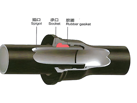 GT-type Joint Ductile Iron Pipe
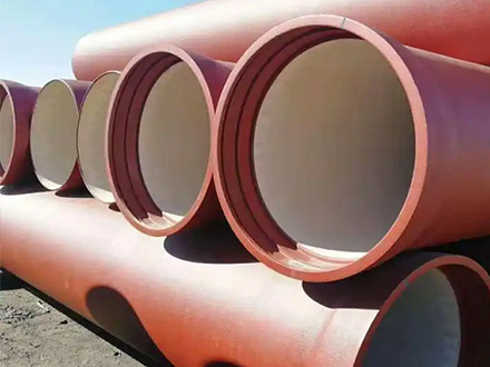
 Sewage Pipe (Ductile Iron Sewage Pipe)
 Special Coating Pipe (Ductile Iron Pipe with Special Coatings)