

Ductile Iron Pipe Push-On Joint vs Flanged Joint: Engineering Selection Guide
Two Joints, Two Different Jobs
The push-on joint vs flanged joint decision is one of those specification choices that looks straightforward on a drawing but has real consequences in the trench. Both joints are fully restrained against axial pullout under normal conditions, both are factory-supplied with the pipe, and both are covered by ISO 2531 and EN 545. But they behave very differently when the project leaves the engineering office and meets a 4-meter-deep trench in the rainy season.
The short version: push-on joints (also called socket-and-spigot, Tyton, or restrained push-on depending on the manufacturer) carry roughly 85–90% of ductile iron pipe installations worldwide. They are faster to install, cheaper per joint, and accommodate angular deflection that flanged joints cannot. Flanged joints exist for specific circumstances — above-ground piping, valve connections, equipment tie-ins, and locations where the joint must be regularly broken for maintenance. Specifying flanged joints where push-on would work doubles the joint cost, slows installation, and rarely improves long-term performance.
This guide covers how to make that push-on joint vs flanged joint ductile iron pipe decision for water supply, irrigation, and force main projects across Southeast Asia and Africa, with field-tested guidance on which to specify under different site conditions.
How Each Joint Actually Works
Push-On Joint (Socket-and-Spigot)
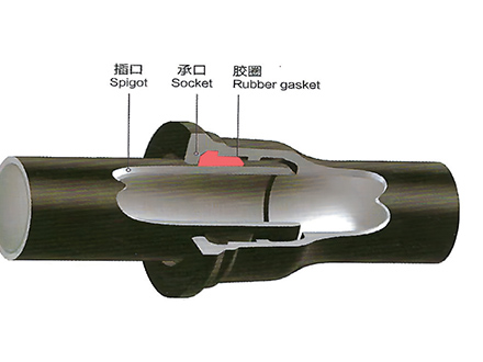
A push-on joint consists of a socket at one end of the pipe, a spigot at the other end, a rubber gasket seated in a groove inside the socket, and a small amount of lubricant applied during assembly. Installation is exactly what the name suggests: the spigot is pushed into the socket by hand or with a small lever, the gasket compresses, and the joint is sealed.
Key engineering characteristics:
- Installation time: 2–4 minutes per joint for DN100–DN300, scaling to 8–12 minutes for DN800 and above
- Angular deflection: typically 3–5 degrees at smaller diameters, reducing to 1.5–2.5 degrees at DN800+, depending on socket design
- Pressure rating: equal to the pipe itself (PFA up to 64 bar for K9 DN100, decreasing with diameter)
- Axial restraint: standard push-on joints are NOT axially restrained — they rely on soil friction, thrust blocks at fittings, or restrained joint systems (often called "locked" or "restrained" push-on) for thrust transfer
Flanged Joint
A flanged joint uses a bolted flange on each pipe end, with a rubber gasket between the flange faces. Bolt torque (typically per ISO 7005-2 or AWWA C110 flange class) compresses the gasket and seals the joint.
Key engineering characteristics:
- Installation time: 15–30 minutes per joint for DN100–DN300, scaling to 60–90 minutes for DN800+ (more bolts, larger torque wrench required)
- Angular deflection: zero in practical terms — flanges must meet face-to-face within tight tolerance
- Pressure rating: governed by the flange class (PN10, PN16, PN25, PN40) rather than the pipe's K-class
- Axial restraint: fully restrained by the bolts — no thrust block required at the joint itself
The installation time difference alone — 4 minutes versus 20 minutes — is why flanged joints remain a minority choice. On a 10 km transmission main with 6-meter pipe lengths, push-on installation runs about 1,667 joints. At 4 minutes per joint, that is 110 hours of pure jointing time. The same main in flanged would take 550+ hours, plus the cost of torque wrenches, bolt lubrication, and re-torque procedures.
Where Each Joint Is the Right Answer
Use Push-On Joints When:
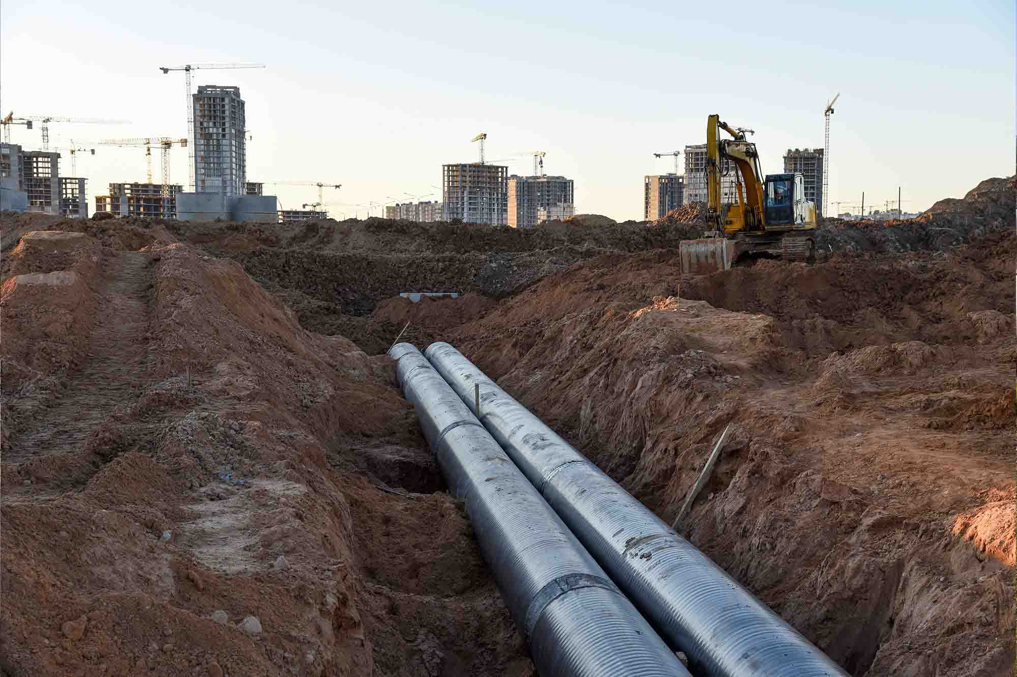
The line is buried. This is the most basic decision rule. Buried ductile iron pipe almost always uses push-on joints. The soil around the pipe provides the thrust restraint, the joint accommodates small ground movement and thermal expansion, and installation speed is high.
The route is long and straight. Transmission mains from a treatment plant to a reservoir, or trunk distribution along a road, are classic push-on applications. Deflection at each joint accumulates over long runs, allowing the pipeline to follow gentle curves without purchasing fabricated bends.
The pipe will not be regularly disassembled. Push-on joints are not designed for repeated assembly and disassembly. The gasket takes a compression set after the first installation, and re-lubrication is awkward. For permanent installations, this is a non-issue.
Above-ground with proper support and thrust blocks. Pump station suction and discharge lines inside a station building can use push-on joints if the layout is fixed and the pipe runs are supported by pipe shoes. Thrust blocks at every fitting are mandatory — push-on joints do not transfer thrust through the joint itself.
Use Flanged Joints When:
Connecting to equipment, valves, and meters. Flanged joints are the standard interface for gate valves, butterfly valves, check valves, flow meters, and pump connections. The valve body has a flange face; the pipe must match. This is the single largest use of flanged joints in any pipeline project — and it is unavoidable.
The pipe is above-ground and exposed to thermal expansion. Flanged joints with proper anchor points and expansion joints accommodate thermal cycling better than push-on, which can creep out of the socket under repeated thermal movement. For exposed pipework on bridge crossings, in treatment plant galleries, or in valve chambers, flanged is the safer choice.
Regular maintenance access is required. If the pipeline includes sections that need periodic disassembly — for example, a bypass line around a treatment unit, or a strainer that must be cleaned annually — flanged joints make the maintenance work possible.
High-pressure vertical or steep-incline runs. On a penstock or a tall riser, the axial thrust from internal pressure can overcome the friction holding a push-on joint in place. Flanged joints with proper anchoring eliminate this risk. For penstocks above PN25, flanged is standard practice.
The Pressure Class Question
There is a common misconception that flanged joints are rated for higher pressure than push-on. They are not — both joints are tested at the same hydrostatic pressure during manufacture. The difference is in how they transfer axial thrust.
A flanged joint is restrained by the bolts. The internal pressure trying to push the pipe ends apart is transmitted through the flange faces, the bolts, and back into the connected pipe or equipment. No thrust block is needed at the joint.
A push-on joint is restrained by the socket and gasket friction, plus the surrounding soil. For most buried applications, this is more than sufficient. But at fittings (bends, tees, reducers, dead ends), the pipeline must be restrained against the axial thrust from internal pressure. This is done with concrete thrust blocks cast against the fitting and the undisturbed soil behind it.
A common specification error on small-diameter distribution networks is to over-design thrust blocks for push-on mains. The actual thrust at a 90-degree bend in a DN200 K9 pipe operating at 10 bar is approximately 4,000 kg — a 1.5m × 1.5m × 0.4m concrete block handles this comfortably. Engineers sometimes specify blocks three or four times this size, increasing material cost and excavation time without any engineering benefit.
Installation and Lifecycle Cost Comparison
For a DN300 K9 pipe, typical 2025–2026 pricing in Southeast Asia:
| Item | Push-On Joint | Flanged Joint |
|---|---|---|
| Pipe unit cost (per meter) | baseline | +18–25% (flange cast on the pipe end) |
| Joint installation time | 3–4 minutes | 20–30 minutes |
| Bolts, gaskets, lubricant per joint | minimal | $8–15 per joint (DN300) |
| Thrust block required | Yes (at fittings) | No (joint is self-restrained) |
| Field equipment needed | Lever bar, lubricant | Torque wrench, lifting gear for large sizes |
| Joint leak rate (in service) | Very low if gasket seated correctly | Low if bolts torqued and re-torqued properly |
Over a 5 km DN300 transmission main with 833 joints (6m pipe length), the installed cost difference is roughly 12–18% in favor of push-on, after accounting for joint material, labor, and thrust blocks. The differential is smaller for above-ground or short-run applications, but push-on remains cheaper almost everywhere it can technically be used.
Field Cases Worth Remembering
The case studies below are composite scenarios drawn from typical project configurations and field experience.
Case 1: River crossing in Cambodia. A 280-meter DN500 K9 pipe section crossed a river on a pipe bridge. The original specification used flanged joints throughout to simplify future replacement of individual pipe sections. After two years of service, three of the flange gaskets failed during the dry season — likely due to thermal cycling on the exposed pipework combined with bolt relaxation. The flanged joint was the correct choice for accessibility, but the maintenance team had not implemented a re-torque schedule. Lesson: flanged joints on exposed pipework require an annual bolt re-torque and gasket inspection program, or specify a more robust gasket material (EPDM instead of SBR for higher temperature resistance).
Case 2: Urban distribution in Lagos. A DN150–DN300 distribution network was installed with push-on joints throughout, including the valve connections. After eight months, two of the gate valves showed leakage at the body-to-flange connection. The valves themselves were flanged-end gate valves, but the contractor had installed a push-on-to-flange adapter at each valve location. One of these adapters failed because the adapter was a different manufacturer's product than the pipe, and the dimensional tolerance at the spigot was slightly off. Lesson: when connecting push-on pipe to flanged valves, use a single-source manufacturer for the pipe AND the adapter, or use a flanged pipe spool at the valve rather than a push-on adapter. Mixing brands at transition points is a common source of leaks.
Case 3: Pump station discharge in Tanzania. A DN400 K9 pump station discharge line was specified with flanged joints throughout the 60-meter above-ground section, then transition to push-on for the 4 km buried run. The flanged section was the right call — above-ground, accessible, and tied into the pump and valve manifold. But the contractor installed the flanged pipe without proper pipe shoes, and after one year of thermal cycling, one joint developed a 2-degree angular misalignment that cracked a flange. Lesson: flanged joints in above-ground service require proper pipe support (shoes, hangers, guides) at the spacing recommended by the manufacturer, typically every 6–9 meters for DN400. The pipe support design is part of the flanged joint specification — not an optional add-on.
Practical Recommendations for Push-On Joint vs Flanged Joint Ductile Iron Pipe Specification
1. Default to push-on for all buried pipe. Specify flanged only where required by equipment or maintenance needs. This sounds obvious, but it is the single most common cost-saver in pipeline specification. Reviewing the bill of materials, flanged pipe is sometimes ordered by default because the engineer did not think through the alternative. Push-on should be the starting point.
2. For valve connections, use a flanged pipe spool rather than a flanged valve directly connected to a push-on pipe. This isolates the valve in a short flanged section and keeps the rest of the line in push-on. It also makes valve replacement easier — you unbolt the spool, replace the valve, and re-bolt. No need to disturb the push-on line on either side.
3. For above-ground pipework, pair the flange specification with a pipe support drawing. Submit the support layout (shoes, hangers, guides, anchors) at the same time as the pipe layout drawing. If the supports are missing or undersized, the flanged joints will fail prematurely regardless of the bolt torque.
4. For restrained push-on systems (high-pressure, steep grades, or fittings without thrust blocks), verify the restraint system is rated for the operating pressure and soil conditions. Restrained push-on joints use either a grip ring inside the socket or a welded-on restraint ring, and they carry specific pressure ratings. A DN600 restrained push-on at 16 bar requires a different system than at 10 bar.
5. For distributors, stock push-on pipe and gaskets, not flanged pipe. Push-on is what the bulk of inventory should be. Flanged pipe and fittings are usually project-specific and ordered against confirmed orders.
 GT-type Joint Ductile Iron Pipe
 Sewage Pipe (Ductile Iron Sewage Pipe)
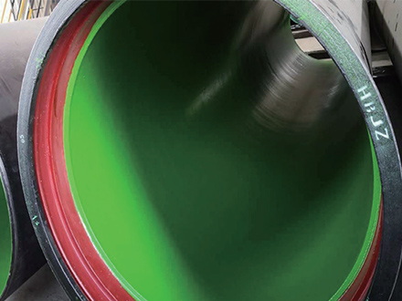 Special Coating Pipe (Ductile Iron Pipe with Special Coatings)